A plate heat exchanger is one of the most efficient and widely used thermal systems in modern industrial infrastructure. Whether it is HVAC, food processing, dairy, pharmaceuticals, chemical plants, utilities, or industrial cooling, a plate heat exchanger plays a critical role in maintaining process temperatures, improving energy efficiency, and reducing operating costs.
At SRJ Heatt Exchangers India Pvt Ltd, we work with industries that need dependable and performance-focused thermal transfer systems. This detailed guide covers the plate heat exchanger working principle, plate heat exchanger diagram, key components, design logic, industrial use cases, maintenance practices, and buyer-focused insights.
What Is a Plate Heat Exchanger?
A plate heat exchanger is a compact thermal system that transfers heat between two fluids using multiple corrugated metal plates arranged in a frame assembly.
Each plate forms a channel through which hot and cold fluids flow in alternate paths. These fluids never mix directly. Instead, heat passes through the plate material from one fluid to the other.
This design offers:
- high thermal transfer efficiency
- compact footprint
- reduced energy consumption
- modular expansion
- easier maintenance
Compared with conventional bulky thermal systems, a plate heat exchanger provides significantly better heat transfer in less installation space.
Plate Heat Exchanger Working Principle
The plate heat exchanger working principle is based on indirect heat transfer.
Two fluids flow through alternate channels created by thin corrugated plates.
- the hot fluid flows through one channel
- the cold fluid flows through the adjacent channel
- the metal plate transfers heat between them
This plate heat exchanger working principle ensures that the fluids remain separate while allowing efficient temperature exchange.
The corrugation pattern on the plates creates turbulence, which increases the heat transfer coefficient and improves overall performance.
Simple Working Process
- Hot fluid enters through inlet nozzle
- Cold fluid enters alternate channel
- Heat transfers through the plate surface
- Temperature equalization occurs
- Both fluids exit through separate outlets
This plate heat exchanger working principle is commonly used where fast and efficient heat transfer is required.
Plate Heat Exchanger Diagram
A plate heat exchanger diagram is extremely important for technical understanding, installation, and maintenance.
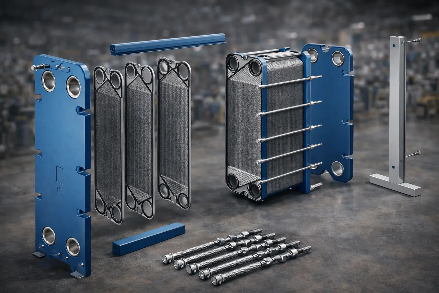
A standard plate heat exchanger diagram includes:
- frame plate
- movable pressure plate
- tightening bolts
- guide bar
- support column
- corrugated plates
- gasket arrangement
- fluid inlet and outlet nozzles
Simplified Flow Diagram
| Component | Function |
| Inlet Nozzle | Fluid entry |
| Corrugated Plates | Heat transfer surface |
| Gasket Channel | Fluid sealing and flow path |
| Outlet Nozzle | Fluid discharge |
| Frame Assembly | Mechanical support |
A proper plate heat exchanger diagram helps engineers identify:
- fluid flow direction
- plate sequence
- gasket placement
- maintenance access points
For procurement and engineering approval, a clear plate heat exchanger diagram is highly valuable.
Counter Flow vs Parallel Flow
The plate heat exchanger working principle generally uses counter-flow arrangement.
Counter Flow
Hot and cold fluids move in opposite directions.
Benefits:
- higher thermal efficiency
- better temperature approach
- reduced energy loss
Parallel Flow
Both fluids move in the same direction.
Used in limited industrial applications.
| Flow Type | Efficiency | Common Use |
| Counter Flow | High | HVAC, industrial cooling |
| Parallel Flow | Moderate | specific applications |
In most cases, counter-flow based plate heat exchanger working principle provides better performance.
Main Components of a Plate Heat Exchanger
A plate heat exchanger consists of multiple engineered parts.
Plates
These are the primary heat transfer surfaces.
Common materials:
- stainless steel
- titanium
- special alloys
Gaskets
Used to seal fluid channels and prevent leakage.
Frame
Provides structural support.
Clamping System
Keeps plates compressed.
Ports and Nozzles
Allow fluid inlet and outlet.
Understanding these components is essential while studying a plate heat exchanger diagram.
Industrial Applications
A plate heat exchanger is widely used across industries.
HVAC Systems
Used in:
- chilled water circuits
- cooling towers
- district cooling plants
Food and Dairy
Used in:
- milk heating
- pasteurization
- beverage processing
Chemical Plants
Used for:
- process cooling
- solvent temperature control
- reaction temperature stabilization
Pharmaceuticals
Maintains precise process temperature.
Utilities
Used in water heating and cooling loops.
This makes the plate heat exchanger working principle commercially important for industrial buyers.
Why Plate Heat Exchanger Diagram Matters for Industry
A proper plate heat exchanger diagram helps in:
- installation planning
- engineering review
- maintenance scheduling
- spare part identification
- troubleshooting
For example, when replacing plates or gaskets, the plate heat exchanger diagram helps maintenance teams quickly identify plate orientation and gasket alignment.
This reduces downtime and service errors.
Performance Advantages
A plate heat exchanger offers several performance benefits.
Key Benefits
- compact design
- high efficiency
- lower footprint
- easy expansion
- low maintenance cost
- faster service access
| Parameter | Benefit |
| Heat Transfer | Very high |
| Space Requirement | Low |
| Maintenance | Easy |
| Efficiency | High |
| Expandability | Excellent |
Because of these advantages, industries increasingly prefer a plate heat exchanger over conventional options.
Design Considerations
While selecting a plate heat exchanger, the following must be evaluated.
Flow Rate
Fluid volume per hour.
Temperature Difference
Required thermal duty.
Pressure Drop
Maximum allowable loss.
Fluid Type
Water, glycol, oil, chemicals, dairy fluid, etc.
Material Compatibility
Corrosion resistance.
These parameters influence both the plate heat exchanger working principle efficiency and long-term service life.
Maintenance and Cleaning
A major advantage of a plate heat exchanger is serviceability.
Maintenance Steps
- isolate unit
- release pressure
- open clamping bolts
- inspect plates
- clean deposits
- replace worn gaskets
- reassemble
The plate heat exchanger diagram is especially useful during maintenance.
Common Problems and Troubleshooting
| Issue | Possible Cause | Solution |
| Leakage | gasket wear | replace gasket |
| Low efficiency | fouling | clean plates |
| Pressure drop | blockage | flush channels |
| uneven temperature | wrong flow | verify diagram |
Why Choose SRJ Heatt Exchangers India Pvt Ltd
At SRJ Heatt Exchangers India Pvt Ltd, we support industrial clients with application-specific solutions.
Our capabilities include:
- custom engineering
- technical consultation
- thermal design support
- replacement parts support
- maintenance guidance
We help clients understand both the plate heat exchanger working principle and plate heat exchanger diagram before final selection.
Buyer Checklist Before Purchase
Before selecting a plate heat exchanger, verify:
- application type
- temperature range
- flow requirement
- plate material
- pressure rating
- service support
Quick Selection Table
| Requirement | What to Check |
| HVAC | capacity and flow |
| dairy | hygiene compatibility |
| chemical | corrosion resistance |
| pharma | precision temperature |
Conclusion
A plate heat exchanger is one of the most efficient industrial thermal solutions available today. Understanding the plate heat exchanger working principle and reviewing a proper plate heat exchanger diagram helps industries improve operational performance, reduce energy costs, and ensure reliable process stability.
With application-specific engineering support from SRJ Heatt Exchangers India Pvt Ltd, industries can implement reliable and scalable thermal systems built for long-term performance.
1. What is a plate heat exchanger?
A plate heat exchanger is a compact thermal system that transfers heat between two fluids using corrugated metal plates.
2. What is the plate heat exchanger working principle?
The plate heat exchanger working principle is based on heat transfer through alternate fluid channels separated by metal plates.
3. Why is a plate heat exchanger diagram important?
A plate heat exchanger diagram helps engineers understand flow direction, plate arrangement, and maintenance points.
4. Where is a plate heat exchanger used?
A plate heat exchanger is widely used in HVAC, food processing, dairy, chemical and industrial cooling systems.
5. What are the main components of a plate heat exchanger?
Main components include plates, gaskets, frame, clamping bolts, inlet and outlet nozzles.
6. What is the difference between counter-flow and parallel flow?
Counter-flow offers higher efficiency, while parallel flow is used in specific low-duty applications.
7. How does a plate heat exchanger improve efficiency?
The corrugated plate surface increases turbulence and improves thermal transfer efficiency.
8. How often should a plate heat exchanger be cleaned?
Cleaning frequency depends on fluid quality and operating conditions, but regular maintenance is recommended.
9. Can I get a plate heat exchanger diagram for installation?
Yes, technical diagrams are used for installation, maintenance and engineering approvals.
10. Why choose SRJ for plate heat exchanger solutions?
SRJ offers industrial-grade design, technical support and reliable thermal solutions for multiple sectors.